Mathematical Details of Antenna Pointing Correction
Pointing an antenna involves many coordinate transformations. The complete chain of coordinate conversions from the standard J2000 right ascension and declination found in a catalogue to the actual commanded azimuth and elevation values sent to the low-level antenna driver is shown below. For illustration the graph includes the KAT-7 Fringe Finder sensor names which correspond to each stage of the chain.
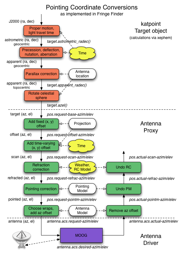
The chain of pointing coordinate conversions.
Two transforms in this chain are explained in more detail below: refraction
correction and pointing correction via a pointing model. These are implemented
in the antenna proxy, based on the katpoint library.
Refraction Correction
The atmosphere refracts incoming electromagnetic waves, which introduces a delay and changes the apparent angle of incidence at the Earth’s surface. The former affects delay tracking in the correlator, while the latter affects antenna pointing. Specifically, the source is perceived to be higher in elevation than it actually is. This section focuses on the pointing aspect of refraction.
KAT-7 and MeerKAT currently focus on the measurement of centimeter-wavelength signals using dishes with a diameter of approximately 15 metres, which implies a beamwidth of the order of one degree of arc. Since the maximum refraction offset is of the order of half a degree at the horizon, this lessens the need for highly accurate refraction models [Mangum1], which is a bigger problem for arrays like ALMA.
At radio frequencies up to about a terahertz, refractive bending is independent of frequency and antenna location, and depends instead on the ambient weather conditions, the main variables being temperature, pressure and relative humidity. There are various atmospheric models that calculate the refraction offset to the elevation angle as a function of elevation angle and these three variables. The most accurate of these are discussed in [Mangum2].
katpoint uses the simple refraction model in the VLBI Field System. The
specific version can be found in Field System version 9.9.2. As noted in the
Field System documentation [Himwich1], the refraction model originated with the
Haystack pointing system, but the documentation for this algorithm seems to have
been lost. It agrees well with the DSN refraction model, though.
The model uses the temperature and humidity to determine the dewpoint temperature, which in turn is used to estimate the partial pressure of water vapour in the atmosphere. The total pressure, partial pressure and temperature are used to estimate the surface refractivity of the atmosphere, which determines the maximum size of the refraction offset. The refraction offset also changes approximately as the cotangent of the elevation angle, with its maximum attained at the horizon. Finally, the elevation angle is corrected for refraction by adding the calculated refraction offset to it.
Pointing Model
An antenna mount typically has small deviations from the ideal which causes discrepancies in its pointing. The antenna pointing model models these discrepancies with a combination of physically justified and ad hoc parameters. The pointing model is fit to a set of pointing measurements, with a unique subset of these parameters typically selected for each mount.
An ideal alt-azimuth mount has a horizontal azimuth ring with a vertical elevation axis perpendicular to it that points at zenith. The usual deviations include biases in azimuth and elevation encoders, a tilt of the azimuth ring relative to the horizon, a tilt of the elevation axis relative to the azimuth ring, misalignment of the RF and pointing axes, and gravitational sag.
Most telescopes rely on the same physical model to correct their pointing, with the only difference being different names for the parameters. This standard model is linear in the parameters, making it useable for small deviations only, and it describes a common set of coordinate system deviations in the mount.
katpoint uses the VLBI Field System version of this model, specialised
for an alt-az mount. The exact description corresponds to the C implementation
of Field System version 9.9.0, which differs slightly from the official
description in [Himwich2] by introducing minor changes to the ad hoc parameters.
The pointing model calculates offsets to the azimuth and elevation angles as a function of azimuth and elevation, which are added to the desired azimuth and elevation to correct them. The azimuth and elevation offset angles are given by
respectively, where \(A\) is the desired azimuth angle, \(E\) is the desired elevation angle and the model parameters are \(P_1\) to \(P_{22}\). All angles and model parameters have units of radians except for \(P_9\) and \(P_{12}\), which are scale factors and therefore unitless. The alt-az mount specialisation makes parameter \(P_2\) meaningless and parameter \(P_{10}\) the same as \(P_8\) and therefore redundant, which reduces the model to 20 parameters.
A short explanation of each parameter is given below together with some nominal causes. The corresponding parameter in the TPOINT pointing model is also pointed out. The parameters can be divided into two groups: six purely geometric terms (\(P_1\), \(P_3\), \(P_4\), \(P_5\), \(P_6\), \(P_7\)) which will normally be present in any alt-azimuth mount, and the rest, which are ad hoc terms modelling gravitional sag and other telescope-specific defects. These ad hoc terms are only enabled in the pointing model if there is sufficient evidence for them (although \(P_8\) is frequently useful).
Pure geometric terms:
\(P_1\) (TPOINT parameter -IA) is the azimuth offset, which includes the effects of encoder bias and tilt around (rotation of the azimuth ring around the vertical axis).
\(P_3\) (TPOINT parameter -NPAE) is the left-right axis skew, which describes non-perpendicularity of the azimuth and elevation coordinate axes. Specifically, it is the angle by which the apparent elevation axis tilts over to the left relative to the azimuth ring, where left means along the meridian with azimuth value 90 degrees less than the desired azimuth. This parameter may also include contributions of elevation and azimuth bearing wobble.
\(P_4\) (TPOINT parameter CA) is the azimuth box offset or left-right collimation error, which represents misalignment of the RF and pointing axes. Specifically, it is the angle by which the RF axis is offset from the pointing axis along the azimuth direction.
\(P_5\) (TPOINT parameter AN) is tilt out, which is a tilt of the azimuth ring towards true North.
\(P_6\) (TPOINT parameter -AW) is tilt over, which is a tilt of the azimuth ring towards true East.
\(P_7\) (TPOINT parameter IE) is the elevation offset, which includes the effects of encoder bias, forward axis skew and elevation box offset. These effects all appear as an elevation offset and cannot be distinguished from each other.
Ad hoc terms:
\(P_8\) (TPOINT parameter ECEC or HECE or -TF) is the maximum symmetric gravitational sag or vertical flexure, which is a downward deflection of the pointing axis experienced when the dish is pointing at the horizon. It models the effect of gravity on the dish structures under the assumption that the structures obey Hooke’s Law. This parameter also includes the cosine component of the elevation centering error, which is misalignment of the elevation encoder and the actual tilt axis and may be traced to eccentricity in the elevation tilt drive wheel or encoder disk, or encoder run-out.
\(P_9\) (TPOINT parameter PEE1) is an excess scale factor in the elevation angle, which occurs when the encoder readout changes faster or slower than the actual antenna position. It is a unitless number.
\(P_{11}\) (TPOINT parameter ECES or HESE) is an asymmetric gravity or flexure term that also includes the sine component of the elevation centering error, which is misalignment of the elevation encoder and the actual tilt axis and may be traced to eccentricity in the elevation tilt drive wheel or encoder disk, or encoder run-out.
\(P_{12}\) (TPOINT parameter -PAA1) is an excess scale factor in the azimuth angle, which occurs when the encoder readout changes faster or slower than the actual antenna position. It is a unitless number.
\(P_{13}\) (TPOINT parameter ACEC or HACA) is the cosine component of the azimuth centering error, a misalignment of the azimuth encoder and the actual azimuth axis that may be due to eccentricity of the azimuth drive wheel or encoder disk, or azimuth encoder run-out.
\(P_{14}\) (TPOINT parameter -ACES or -HASA) is the sine component of the azimuth centering error, a misalignment of the azimuth encoder and the actual azimuth axis that may be due to eccentricity of the azimuth drive wheel or encoder disk, or azimuth encoder run-out.
\(P_{15}\) (TPOINT parameter HECA2) is the cosine component of an elevation nod twice per azimuth revolution.
\(P_{16}\) (TPOINT parameter -HESA2) is the sine component of an elevation nod twice per azimuth revolution.
\(P_{17}\) (TPOINT parameter -HACA2) is the cosine component of azimuth encoder tilt.
\(P_{18}\) (TPOINT parameter HASA2) is the sine component of azimuth encoder tilt.
\(P_{19}\) (TPOINT parameter HECE8) models higher-order distortions in the elevation encoder scale that vary eight times per revolution.
\(P_{20}\) (TPOINT parameter HESE8) models higher-order distortions in the elevation encoder scale that vary eight times per revolution.
\(P_{21}\) (TPOINT parameter -HECA) is the cosine component of an elevation nod once per azimuth revolution.
\(P_{22}\) (TPOINT parameter HESA) is the sine component of an elevation nod once per azimuth revolution.
Jeff Mangum, NRAO, private communication.
Jeff Mangum, “Atmospheric Refractive Signal Bending and Propagation Delay,” ALMA Memo, 26 January 2009.
Himwich, “Station Programs,” Mark IV Field System Reference Manual, Version 8.2, 1 September 1993, available at ftp://gemini.gsfc.nasa.gov/pub/fsdocs/stprog.pdf
Himwich, “Pointing Model Derivation,” Mark IV Field System Reference Manual, Version 8.2, 1 September 1993, available at ftp://gemini.gsfc.nasa.gov/pub/fsdocs/model.pdf